Understanding Solar Thermal Cycling Panels and Their Role in Florida’s Climate
In the Florida Panhandle, the daily dance between the Gulf’s breezy mornings and the scorching afternoon sun creates a unique environment for solar installations. This region, especially cities like Pensacola and Tallahassee, experiences temperature swings that can exceed 30 °F (about 17 °C) within a single day. When solar panels are exposed to such rapid changes, they undergo what engineers call “thermal cycling.” Over the lifespan of a system, these cycles of expansion and contraction can subtly, yet cumulatively, affect the structural integrity and electrical performance of the panels. For homeowners, businesses, and installers who are considering a long‑term investment, understanding how solar thermal cycling panels behave under these conditions is essential for ensuring reliable power generation for decades to come.
Find us here:
Solar Cost Calculator – Florida Panhandle Only
* Estimate based on $3.25 per watt for solar installation.
* For Tesla Powerwall 3 Batteries, $15,000 for the first battery, $12,000 for each additional battery.
* Other variations and types of Batteries are available.
What Is Thermal Cycling and Why It Matters for Solar Panels
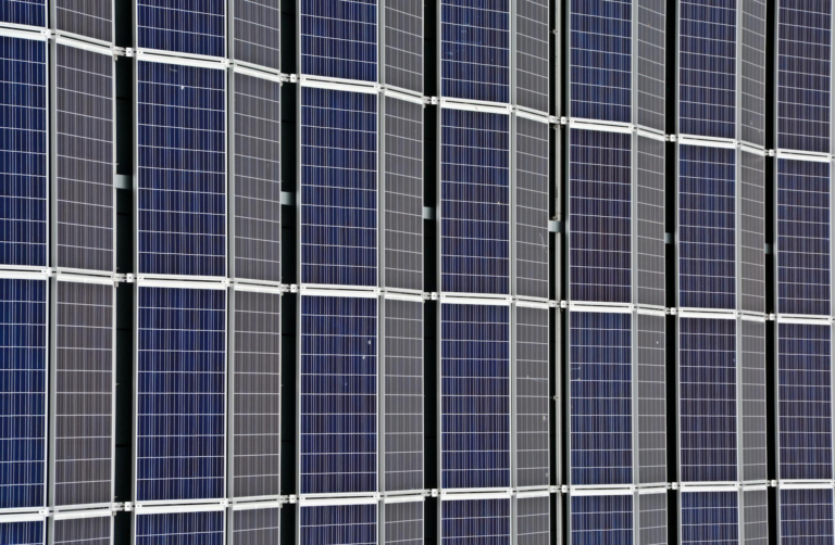
Thermal cycling refers to the repeated heating and cooling of a material, which causes it to expand when heated and contract when cooled. In the context of photovoltaic (PV) modules, each cycle creates microscopic stresses at the interfaces between the glass front sheet, the encapsulant (usually EVA), the solar cells, and the back sheet. Over time, these stresses can lead to delamination, micro‑cracks in the silicon, and degradation of the conductive pathways that link cells together. Solar thermal cycling panels are specifically engineered to tolerate more aggressive temperature ranges, but even they are not immune to the relentless push‑pull of daily temperature fluctuations common in the Panhandle.
Temperature Fluctuations in Pensacola and Tallahassee
Both Pensacola and Tallahassee sit just north of the Tropic of Cancer, placing them in a subtropical zone where humidity and heat dominate the summer months, while winter mornings can be surprisingly cool. On a typical summer day, surface temperatures on a rooftop can rise from the low 70 °F (21 °C) in the early morning to well above 100 °F (38 °C) by mid‑afternoon, then dip back down as the sun sets. In winter, the same panels might experience a rise from the mid‑40s °F (7 °C) to the high 60s °F (around 20 °C). These swings happen repeatedly, day after day, year after year, creating thousands of thermal cycles over a panel’s service life.
Material Expansion and Contraction: The Science Behind the Stress
Every component of a solar module has its own coefficient of thermal expansion (CTE). Glass typically expands at about 9 × 10⁻⁶ /°C, while the polymeric encapsulant may expand at roughly 50 × 10⁻⁶ /°C. Silicon cells have a CTE near 2.6 × 10⁻⁶ /°C. When the sun heats the panel, the glass and encapsulant try to expand more than the silicon, creating shear forces at their bonding interfaces. Conversely, as the panel cools, these forces reverse. Over thousands of cycles, the repeated shear can cause the encapsulant to lose adhesion, leading to moisture ingress, which accelerates corrosion of the metallic contacts and the busbars that carry current between cells.
Impact on Electrical Interconnections and Power Output
Solar thermal cycling panels rely on fine metallic ribbons and solder joints to connect individual cells into a functional module. These connections are particularly vulnerable to fatigue because they are thin, often only a few micrometers thick, and must accommodate the differential movement of the surrounding materials. Micro‑cracks can develop in the solder or in the busbars themselves, increasing the series resistance of the module. The result is a measurable drop in power output, especially under high‑irradiance conditions when the panel is already operating near its maximum capacity. In extreme cases, a single faulty interconnect can cause a hot‑spot, leading to localized heating that further degrades the cell.
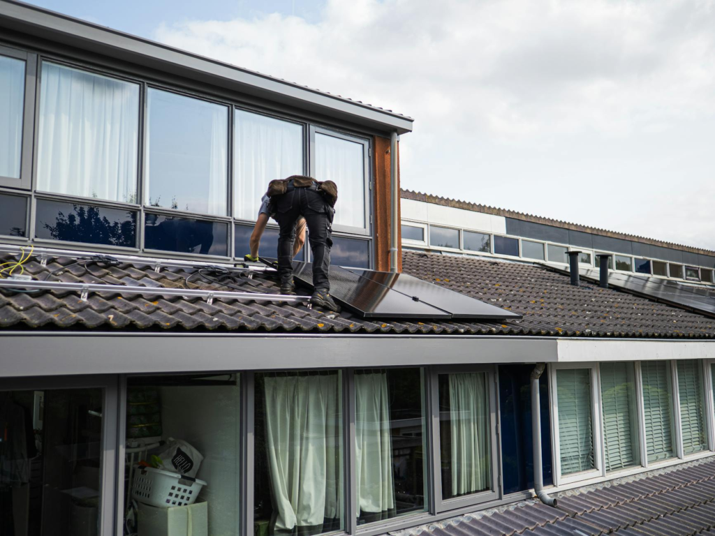
Mounting Systems: The First Line of Defense Against Thermal Stress
The way a solar array is mounted on a roof or ground structure plays a crucial role in mitigating the effects of thermal cycling. Rigid, non‑adjustable mounting rails can transfer the expansion forces directly to the panel frame, amplifying stress at the corners where the frame meets the glass. In contrast, mounting solutions that incorporate flexible brackets, slip‑fit designs, or thermal break materials allow the panel to “breathe” slightly, reducing the mechanical load on the module during temperature changes. For solar thermal cycling panels installed in the Panhandle, selecting a mounting system with built‑in compliance is a best practice that can extend the useful life of the system.
Practical Strategies to Reduce Thermal Cycling Damage
- Choose panels with a proven track record of high CTE compatibility between glass, encapsulant, and cell materials.
- Specify mounting hardware that includes elastic or slip‑fit components to accommodate expansion.
- Implement a regular inspection schedule, focusing on visual signs of delamination, discoloration, or hot‑spots.
- Use temperature‑resilient back sheets, such as fluoropolymer‑based options, which resist cracking under repeated stress.
- Consider installing a micro‑inverter or power optimizer at the module level to isolate the impact of a single underperforming panel.
Design Considerations Specific to the Florida Panhandle
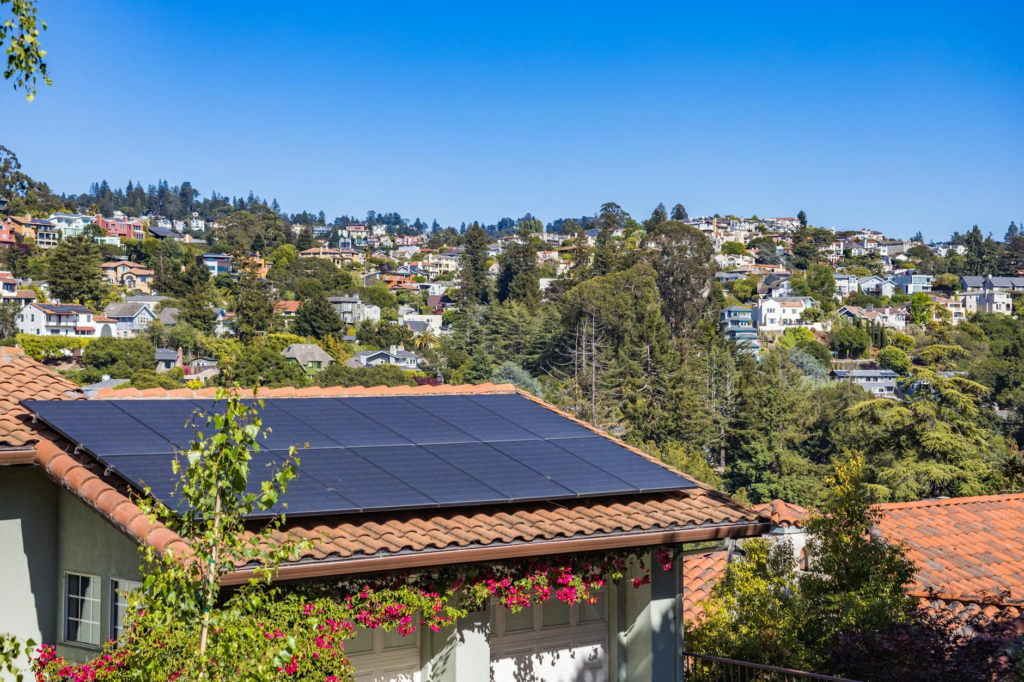
Designing a solar array for Pensacola or Tallahassee requires more than just picking the highest‑efficiency panels. The local climate calls for a balanced approach that weighs performance against durability. First, orientation and tilt should be optimized not only for solar irradiance but also for airflow. Better ventilation under the panels reduces the temperature differential between the panel surface and the ambient air, lessening the magnitude of each thermal cycle. Second, shading analysis should account for seasonal variations; a tree that casts a shadow in winter may be absent in summer, altering the thermal load distribution across the array.
Third, the choice between monocrystalline and polycrystalline modules can influence thermal behavior. Monocrystalline panels typically have a slightly lower CTE mismatch due to their thinner glass and higher-quality encapsulant, making them marginally more resistant to thermal fatigue. However, polycrystalline panels often come at a lower cost, which can be a decisive factor for large‑scale installations. Finally, integrating a monitoring system that logs temperature, voltage, and current at the module level enables early detection of performance degradation that may be linked to thermal cycling.
Monitoring and Maintenance: Keeping an Eye on Thermal Effects
Modern solar monitoring platforms provide real‑time data that can reveal subtle trends indicating thermal stress. For instance, a gradual increase in the temperature coefficient of power (the rate at which output drops with temperature) can signal that the encapsulant is losing its effectiveness. Maintenance crews should prioritize cleaning schedules that avoid high‑temperature periods, as hot water can exacerbate thermal shock. Moreover, thermal imaging inspections performed during the cooler early morning hours can highlight hidden hot‑spots that are not visible to the naked eye, allowing technicians to address issues before they become catastrophic.
Comparison of Common Panel Types Under Thermal Cycling
| Panel Type | Typical CTE Mismatch | Observed Longevity in High‑Cycle Zones |
|---|---|---|
| Monocrystalline (high‑grade) | Low | 25 + years |
| Polycrystalline (standard) | Moderate | 20–25 years |
| Thin‑film (CdTe) | High | 15–20 years |
The table above illustrates that monocrystalline solar thermal cycling panels generally exhibit the lowest coefficient of thermal expansion mismatch, translating to longer service lives in environments with frequent temperature swings. While thin‑film technologies offer cost advantages, their higher CTE mismatch makes them more susceptible to fatigue in the Panhandle’s daily temperature variations.
Emerging Technologies to Combat Thermal Fatigue
Researchers are actively developing next‑generation PV technologies that aim to reduce thermal cycling impact. One promising avenue is the use of glass‑glass modules, where both the front and back of the panel are made of tempered glass, eliminating the need for a polymer back sheet that can degrade over time. Another innovation involves encapsulants based on silicone or thermoplastic polyurethanes, which possess higher elasticity and better adhesion under temperature stress. Additionally, bifacial panels that capture light from both sides can be installed with elevated mounting structures that promote airflow, further mitigating temperature spikes.
Frequently Asked Questions About Solar Thermal Cycling Panels
- How many thermal cycles can a typical panel endure? Most manufacturers rate their modules for at least 20,000 cycles, which translates to roughly 20–30 years in a typical climate.
- Does a warranty cover damage from thermal cycling? Standard performance warranties often include provisions for degradation due to thermal stress, but physical damage from extreme cycles may be excluded.
- Can retrofitting existing mounts improve thermal resilience? Yes, adding flexible brackets or thermal breaks to older mounting systems can reduce stress transfer to the panels.
- Is there a noticeable performance loss after many cycles? A gradual decline of 0.5–1 % per year is typical, but accelerated loss may indicate underlying thermal fatigue.
By understanding the mechanisms behind solar thermal cycling panels and implementing design, installation, and maintenance practices tailored to the Florida Panhandle’s climate, system owners can safeguard their investment and enjoy reliable, clean energy for decades.
Conclusion: Temperature fluctuations across Pensacola and Tallahassee create expansion and contraction cycles that directly influence the longevity of solar installations. Selecting the right solar thermal cycling panels, pairing them with compliant mounting hardware, and maintaining vigilant monitoring are the three pillars of long‑term reliability in this region.