Introduction
When homeowners in the Florida Panhandle invest in solar power, they often focus on panel placement, inverter capacity, and financing options. Yet one hidden factor can quietly erode the system’s performance over time: the length of the wiring that carries electricity from the rooftop array to the inverter and ultimately to the home’s electrical panel. This phenomenon, known as voltage drop, directly influences solar wire run efficiency. Even a modest increase in wire length can shave off a few percent of the energy that would otherwise be captured and converted, which adds up to noticeable losses on a yearly basis. Understanding how wire runs affect solar efficiency helps homeowners make smarter design choices, select appropriate cable sizes, and plan installations that maximize the return on their investment while keeping the system compliant with local electrical codes.
Find us here:
Solar Cost Calculator – Florida Panhandle Only
* Estimate based on $3.25 per watt for solar installation.
* For Tesla Powerwall 3 Batteries, $15,000 for the first battery, $12,000 for each additional battery.
* Other variations and types of Batteries are available.
Understanding Wire Length and Its Impact
Why wire length matters
The distance electricity must travel through a conductor is a fundamental determinant of solar wire run efficiency. As current moves along copper or aluminum conductors, it encounters resistance that converts some of the electrical energy into heat. The longer the wire, the greater the resistance, and the more pronounced the voltage drop. In a typical residential solar installation, the distance from the array to the inverter can range from a few feet to over 100 feet, especially when panels are placed on a detached garage or a separate structure. Each additional foot adds a small but cumulative loss, which can be especially significant in the hot, humid climate of the Florida Panhandle where resistivity of conductors can increase slightly with temperature.
Electrical resistance basics
Resistance (measured in ohms) is determined by three key variables: the material of the conductor, its cross‑sectional area (gauge), and its length. Copper, the most common material for solar wiring, offers low resistance, while aluminum, though lighter and cheaper, has higher resistance and therefore can reduce solar wire run efficiency more quickly if not sized correctly. The American Wire Gauge (AWG) system quantifies conductor size; a lower AWG number indicates a thicker wire with less resistance. For example, a 10‑AWG copper cable has roughly half the resistance of a 12‑AWG cable of the same length. Selecting the appropriate gauge based on expected current and distance is essential to preserving the energy produced by the panels.
Voltage drop and its effect on panel output
Voltage drop is calculated as the product of current (amps), resistance (ohms), and the number of conductors in the circuit (typically two for a single‑phase DC run). Even a 2‑3 percent drop can shift the operating point of a solar module, reducing its maximum power point (MPP) and lowering overall system output. Solar inverters are designed to operate within a specific voltage window; if the voltage arriving at the inverter falls below this window due to excessive wire length, the inverter may throttle power or shut down to protect itself. Consequently, the longer the wire run, the more likely the system will experience reduced performance, especially during peak sunlight hours when current is highest.
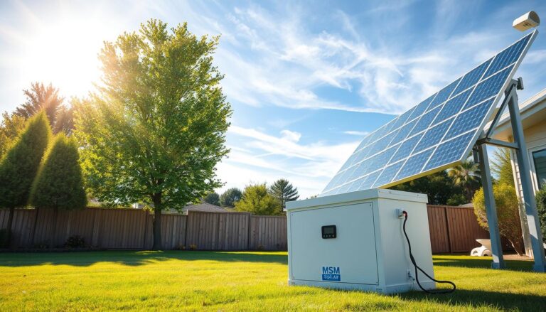
Real‑World Impact in the Florida Panhandle
The Florida Panhandle presents a unique set of challenges and opportunities for solar installations. Many homes feature detached garages, screened porches, or even separate summer cottages that are ideal locations for mounting solar arrays. While these sites can capture abundant sunlight, they often require longer wire runs to connect the panels to the main electrical service. In practice, a 75‑foot DC cable run using 12‑AWG copper can incur a voltage drop of roughly 2.5 percent under typical operating currents, translating to an annual energy loss of 5‑10 kilowatt‑hours per kilowatt of installed capacity. Over a 10‑year lifespan, that loss can amount to several hundred dollars, directly affecting the system’s payback period. By optimizing wire routes and selecting the correct conductor size, homeowners can significantly improve solar wire run efficiency and protect their investment against these hidden losses.
Practical Strategies for Maximizing Efficiency
Best practices for minimizing loss
To safeguard solar wire run efficiency, installers should follow several best‑practice guidelines. First, locate the inverter as close as possible to the array to reduce the length of the high‑current DC run. When this isn’t feasible, consider using a DC combiner box positioned midway to split the array into smaller strings, each with shorter individual runs. Second, choose a conductor gauge that meets or exceeds the recommendations of the National Electrical Code (NEC) Table 310.15(B)(16) for the expected current and distance. In many cases, upgrading from 12‑AWG to 10‑AWG copper for runs longer than 50 feet provides a noticeable boost in efficiency without a substantial cost increase. Finally, avoid sharp bends, excessive pulling tension, and exposure to direct sunlight or moisture, all of which can degrade cable performance over time.
Choosing the right conductor size
The decision on wire gauge should be driven by a combination of current calculations, distance, and temperature rating. For a typical 5 kW residential system producing up to 9 amps per string, a 12‑AWG copper cable is acceptable for runs up to 30 feet with less than 1 percent voltage drop. However, for runs extending beyond 50 feet, upgrading to 10‑AWG or even 8‑AWG copper can keep voltage drop under the recommended 2‑percent threshold, thereby preserving solar wire run efficiency. Aluminum conductors, while lighter, generally require a gauge one or two sizes larger than copper to achieve comparable resistance levels, making them less ideal for tight residential spaces where conduit fill is a concern.
Using connectors and junction boxes correctly
Even the best‑sized cable can suffer efficiency losses if connections are poor. Loose or corroded connectors increase resistance at critical points, effectively creating a “hot spot” that can offset the benefits of a well‑chosen wire gauge. It is essential to use UV‑rated, waterproof MC4 connectors for panel interconnections and to torque all connections to the manufacturer’s specifications. Junction boxes should be mounted in ventilated, dry locations, and any splices must be made with approved solar-rated connectors or soldered and heat‑shrink protected. Properly installed connections ensure that the entire length of the wire run contributes positively to system performance, maintaining high solar wire run efficiency throughout the lifespan of the installation.
Monitoring and Maintenance
Once the system is operational, ongoing monitoring helps detect any degradation in solar wire run efficiency that may arise from aging cables, connector corrosion, or unexpected temperature spikes. Modern inverters and monitoring platforms provide real‑time voltage and current data for each string, allowing installers and homeowners to spot voltage drop trends early. If a particular string consistently shows lower voltage at the inverter than expected, it may indicate a problem with the wire run that warrants inspection. Regular visual checks of conduit, cable trays, and junction boxes for signs of wear, rodent damage, or moisture intrusion further protect the system’s efficiency and safety.
Quick Reference: Typical Voltage Drop by Distance
| Wire Length (feet) | Gauge | Estimated Voltage Drop (%) |
|---|---|---|
| 0–30 | 12 AWG copper | ≤1.0% |
| 31–60 | 12 AWG copper | 1.0–1.5% |
| 61–90 | 10 AWG copper | ≤1.5% |
| 91–120 | 10 AWG copper | 1.5–2.0% |
Frequently Asked Questions
- Can I use aluminum wire to save money? Aluminum can be used if you increase the gauge to compensate for its higher resistance, but copper remains the preferred choice for most residential solar applications due to its lower voltage drop and better durability.
- How often should I check my wire connections? Perform a visual inspection at least twice a year and review inverter monitoring data quarterly to catch any abnormal voltage drops early.
- Does temperature affect wire resistance? Yes, higher ambient temperatures increase resistance slightly, which can marginally reduce solar wire run efficiency during the hottest months.
- Is it worth upgrading to a larger gauge for long runs? Absolutely; the modest additional cost of a thicker conductor often pays for itself through increased energy production and a shorter payback period.
- What role does conduit play in efficiency? Properly sized conduit protects cables from physical damage and UV exposure but does not affect electrical resistance; however, using conduit that forces tighter bends can increase resistance at bend points.
By paying close attention to the length, size, and quality of the wiring that connects your solar panels to the inverter, you can preserve the maximum amount of harvested energy. Optimizing solar wire run efficiency is a straightforward yet powerful way to ensure that every ray of sunshine translates into usable power for your home, especially in the sunny but sometimes challenging environment of the Florida Panhandle.