

When a homeowner or business in the Gulf Coast decides to go solar, the excitement often centers on clean energy and lower utility bills. However, a critical engineering aspect lies behind the scenes: ensuring that the mounting system can resist the forces of wind. For installations near the coast, where breezes can quickly become gusts, understanding wind uplift solar systems is essential. Proper calculations protect the roof, the panels, and the people who rely on them. This article explores why wind uplift calculations are not optional, how they are performed, and what specific challenges coastal locations like Pensacola and Panama City present.
Find us here:
Solar Cost Calculator – Florida Panhandle Only
* Estimate based on $3.25 per watt for solar installation.
* For Tesla Powerwall 3 Batteries, $15,000 for the first battery, $12,000 for each additional battery.
* Other variations and types of Batteries are available.
Understanding Wind Uplift on Solar Arrays
What Is Wind Uplift?
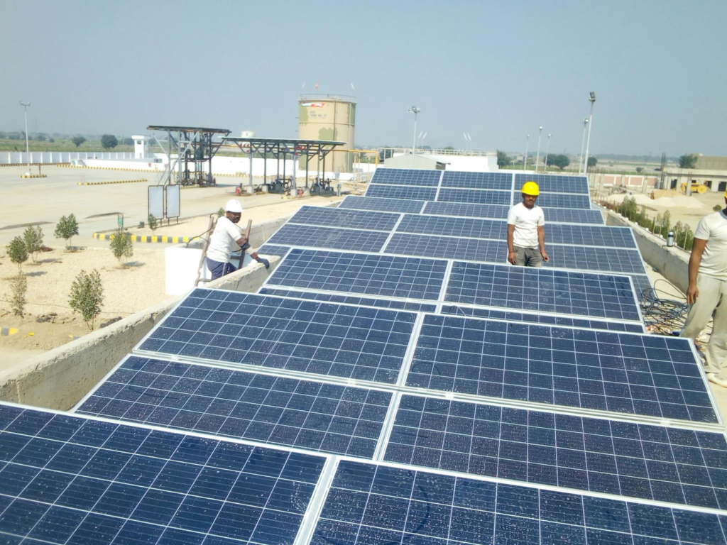
Wind uplift is the upward force generated when wind flows over a surface and creates a pressure differential. In the context of solar installations, the panels act like a sail, catching wind and producing a lifting force that can try to peel the mounting hardware away from the roof. This phenomenon is especially pronounced on flat or low‑slope roofs where the wind can travel unimpeded across the panel surface. The magnitude of uplift depends on wind speed, panel size, roof pitch, and the exposure of the site. Ignoring this force can lead to mounting failures, cracked panels, and even roof collapse under extreme conditions.
How Wind Forces Are Measured
Engineers quantify wind forces using standards such as ASCE 7, which provides equations for determining design wind pressure based on regional wind speed maps, exposure categories, and importance factors. The calculation begins with the basic wind speed (often a 3‑second gust) for the specific location, then adjusts for terrain roughness, building height, and shielding effects. The resulting pressure, expressed in pounds per square foot (psf), is applied to the projected area of the solar array to estimate the uplift force. These numbers become the foundation for selecting appropriate mounting hardware, fastening methods, and roof reinforcement strategies.
Why Calculations Are Critical for Safety
Without precise wind uplift solar systems calculations, installers are essentially guessing the forces their structures will face. This guesswork can have serious consequences. An undersized mounting system may detach during a storm, causing panels to fall and create hazardous debris. Moreover, the sudden removal of weight from a roof can alter load distribution, leading to hidden damage that manifests months later. In coastal areas where wind events are frequent, the risk multiplies. Accurate calculations ensure that each component—from the base plates to the bolts—has the capacity to resist the anticipated uplift, preserving the integrity of both the roof and the solar investment.
Structural Integrity
The roof is designed primarily to support downward loads such as the weight of roofing materials, snow, and occupants. Adding a solar array introduces both additional dead load and a dynamic uplift load. Engineers must verify that the roof framing can handle the combined stresses without excessive deflection or failure. This often involves reinforcing rafters, adding blocking, or selecting mounting brackets with higher shear capacity. When wind uplift solar systems are properly calculated, the design can accommodate these forces, preventing premature fatigue and extending the lifespan of the installation.
Code Compliance
Local building codes in Florida, including the Florida Building Code (FBC), reference ASCE 7 for wind design. Installers must submit wind uplift calculations as part of the permitting process. Failure to provide accurate data can result in denied permits, costly rework, or legal liability if an installation fails during a storm. By performing thorough wind uplift solar systems analysis, contractors demonstrate compliance, streamline approvals, and protect themselves from potential lawsuits.
Regional Factors in Pensacola and Panama City
Pensacola and Panama City sit on the Gulf of Mexico, a region known for high wind speeds, especially during hurricane season. The coastal exposure category is typically classified as Exposure C or D, indicating minimal shielding from surrounding terrain. This classification significantly raises the design wind pressure compared to inland locations. Additionally, the warm, moist climate contributes to rapid corrosion of metal components, meaning that mounting hardware must be both strong and resistant to salt‑laden air.
Coastal Wind Patterns
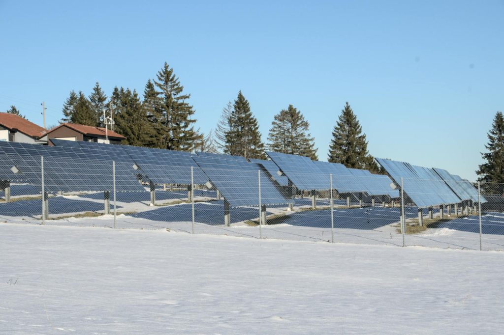
Sea breezes in the Gulf can reach sustained speeds of 15–20 mph, with gusts exceeding 40 mph during storms. When these gusts encounter a solar panel, the uplift force can be amplified by the panel’s angle and surface area. Engineers use site‑specific wind data from NOAA or local weather stations to select the appropriate basic wind speed for calculations. In many cases, the design speed for wind uplift solar systems in these coastal cities is set at the 100‑year return period to ensure resilience against extreme events.
Salt Air and Corrosion
Salt particles in the air accelerate the corrosion of steel fasteners and aluminum brackets. Even when the structural capacity is adequate, weakened connections can fail under uplift loads. Selecting corrosion‑resistant materials—such as stainless steel or hot‑dip galvanized components—and applying protective coatings are essential steps that complement the engineering calculations. Properly accounting for these environmental factors ensures that wind uplift solar systems remain secure throughout their service life.
The Calculation Process
Performing wind uplift calculations involves a systematic workflow that blends data collection, code application, and engineering judgment. The goal is to produce a set of design values that guide the selection of mounting hardware, fastening patterns, and any necessary roof reinforcement. Below is an overview of the typical steps taken by qualified engineers and installers.
Gathering Site Data
The first step is to obtain accurate site information. This includes the roof geometry (pitch, dimensions, and material), the layout of the solar array (panel dimensions, spacing, and orientation), and the local wind speed data. Satellite imagery, on‑site surveys, and architectural drawings are used to compile a comprehensive model of the installation area. Accurate data is crucial because even small errors in roof pitch or panel tilt can lead to significant deviations in uplift force estimates.
Selecting Design Wind Speed
Using the ASCE 7 wind speed maps, engineers identify the basic wind speed for the site’s location and exposure category. For coastal zones like Pensacola, the design speed is often increased to account for the higher probability of extreme gusts. The selected speed is then modified by importance factors that reflect the critical nature of the solar installation—commercial systems may require a higher factor than residential ones.
Applying Uplift Coefficients
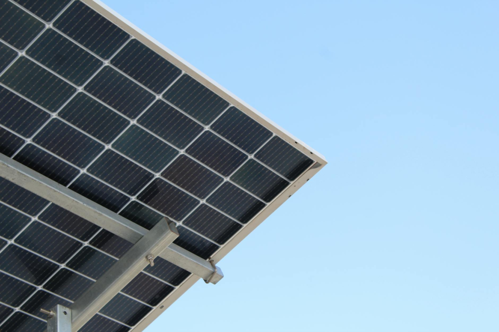
Uplift coefficients (Cp) account for the shape and orientation of the solar panels. Flat‑plate arrays have higher coefficients than tilted installations because they present a larger surface to the wind. The ASCE 7 standard provides tables for these coefficients based on panel angle and exposure. Multiplying the design wind pressure by the appropriate coefficient yields the net uplift pressure acting on each panel, which is then used to size bolts, brackets, and roof penetrations.
- Determine basic wind speed for the location.
- Identify exposure category (typically C or D for coastal sites).
- Calculate design wind pressure using ASCE 7 formulas.
- Apply panel‑specific uplift coefficients.
- Compute total uplift force for each mounting point.
- Select hardware with a safety factor of at least 1.5.
- Verify roof framing can accommodate combined loads.
Common Mistakes and How to Avoid Them
Even experienced installers can overlook critical aspects of wind uplift solar systems design. Recognizing these pitfalls early can save time, money, and safety risks.
Ignoring Roof Pitch
Many calculations assume a flat roof, which underestimates uplift on sloped surfaces. A steeper pitch reduces the effective wind pressure on the panel but increases the component of force acting parallel to the roof plane. Adjusting the uplift coefficient for the actual pitch ensures that fasteners are neither over‑ nor under‑designed.
Underestimating Exposure Category
Coastal sites often fall into higher exposure categories due to the lack of windbreaks. Selecting a lower category can dramatically reduce the calculated wind pressure, leading to insufficient hardware. Always verify the exposure classification with local building officials or a qualified wind engineer.
Benefits of Proper Wind Uplift Planning
Investing effort into accurate wind uplift solar systems analysis yields tangible advantages beyond code compliance. Proper planning enhances the durability of the installation, reduces maintenance costs, and provides peace of mind for property owners.
Longevity of Solar Investment
When mounting hardware is sized correctly, panels remain securely attached for decades, even through severe weather events. This stability protects the photovoltaic modules from micro‑cracks and shading losses that can reduce energy production over time. A well‑engineered system maintains its performance, maximizing the return on investment.
When mounting hardware is sized correctly, panels remain securely attached for decades, even through severe weather events. This stability protects the photovoltaic modules from micro-cracks and shading losses that can reduce energy production over time. A well-engineered system maintains its performance, maximizing the return on investment.
In Gulf Coast regions where storms and hurricanes are part of life, durable mounting systems also reduce the likelihood of emergency repairs after severe weather. Property owners can feel confident knowing their solar array has been designed specifically for the environmental conditions of the area rather than relying on generic national standards.
Reduced Maintenance and Repair Costs
Poorly engineered systems often develop issues gradually. Loose fasteners, shifting rails, water intrusion around penetrations, and damaged roof materials can all stem from inadequate uplift calculations. Over time, these seemingly minor issues can become expensive structural repairs.
By contrast, systems designed with accurate wind uplift solar systems calculations require fewer corrective maintenance visits because the hardware, attachments, and reinforcements are selected appropriately from the start. Investing in proper engineering upfront frequently saves thousands of dollars over the lifespan of the solar installation.
Improved Insurance and Property Value
Insurance providers increasingly examine engineering documentation for solar systems in hurricane-prone areas. Proper uplift calculations can support insurance approvals and may even contribute to better policy terms because the risk of storm damage is reduced.
Additionally, prospective buyers often view professionally engineered solar systems as a valuable asset. A documented installation that complies with Florida codes and wind resistance standards adds credibility and can improve property resale value.
Why Professional Engineering Matters
Although some online calculators claim to simplify wind analysis, true wind uplift solar systems design requires professional expertise. Licensed structural engineers understand how to interpret ASCE 7 provisions, evaluate roof framing conditions, and identify site-specific risks that automated tools may miss.
Every roof behaves differently under wind loads. Factors such as parapet walls, nearby buildings, roof transitions, and local terrain all influence airflow patterns and uplift forces. A professional assessment ensures these variables are considered before installation begins.
Collaboration Between Installers and Engineers
Successful solar projects often involve close coordination between the installer, roofing contractor, and structural engineer. Installers provide the panel layout and mounting details, while engineers verify structural capacity and calculate uplift resistance requirements.
This collaborative approach is especially important in coastal Florida, where permitting departments frequently request stamped engineering drawings before approving solar projects. Early coordination prevents delays and ensures smoother inspections.
Questions Property Owners Should Ask
Before hiring a solar contractor in Pensacola, Panama City, or nearby Gulf Coast areas, property owners should ask a few critical questions:
- Will a licensed engineer perform wind uplift calculations?
- Are the calculations compliant with the latest ASCE 7 and Florida Building Code requirements?
- What exposure category has been assumed for the property?
- Are corrosion-resistant mounting components included?
- Will the contractor provide stamped engineering documents for permitting?
These questions help distinguish experienced professionals from installers who may overlook essential structural considerations.
The Future of Wind-Resistant Solar Design
As solar adoption continues to grow along the Gulf Coast, engineering standards are evolving to address increasingly severe weather patterns. Modern mounting systems are becoming more aerodynamic, reducing uplift forces while improving installation efficiency.
Advances in attachment technology, rail-less systems, and integrated flashing solutions are also helping improve both structural performance and roof waterproofing. However, even the most advanced products still depend on accurate wind uplift solar systems calculations to perform safely under real-world conditions.
Climate Resilience and Renewable Energy
Florida’s push toward renewable energy must go hand-in-hand with resilient infrastructure. Solar systems that cannot withstand coastal wind conditions undermine both safety and sustainability goals. By prioritizing engineering integrity, homeowners and businesses can enjoy clean energy without compromising structural reliability.
Conclusion
For coastal regions like Pensacola and Panama City, wind uplift calculations are not merely a technical requirement—they are a critical safeguard for safety, durability, and long-term performance. Solar panels face tremendous forces during storms, and without accurate engineering, even high-quality systems can fail under pressure.
Proper wind uplift solar systems analysis ensures that mounting hardware, roof structures, and fastening methods are capable of resisting the challenging Gulf Coast environment. From code compliance and corrosion resistance to investment protection and insurance considerations, every aspect of a successful coastal solar installation depends on thoughtful engineering.
Whether installing a small residential array or a large commercial system, working with qualified professionals who understand Florida’s wind requirements is essential. In hurricane-prone regions, strong engineering is just as important as strong sunlight.