Introduction
When designing a solar array, especially in the sunny but often humid climate of the Florida Panhandle, engineers must think beyond just panel selection and inverter sizing. One of the most subtle yet impactful design variables is the distance between successive rows of modules. This distance, known as row spacing, directly influences the amount of self‑shading that occurs throughout the day. Self‑shading reduces the amount of sunlight each panel receives, cutting the overall energy harvest and potentially compromising the financial model of the project. By understanding how solar row spacing self shading behaves under different tilt angles, orientations, and seasonal sun paths, system designers can optimize layouts to capture the maximum possible irradiance while still fitting within site constraints. This article explores the science, the calculations, and the practical guidelines that help you minimize self‑shading losses in both rooftop and ground‑mount installations across the Panhandle.
Find us here:
Solar Cost Calculator – Florida Panhandle Only
* Estimate based on $3.25 per watt for solar installation.
* For Tesla Powerwall 3 Batteries, $15,000 for the first battery, $12,000 for each additional battery.
* Other variations and types of Batteries are available.
Why Row Spacing Matters in Solar Installations
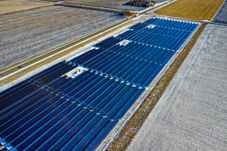
Solar panels are essentially flat surfaces that convert sunlight into electricity. When panels are placed too close together, the shadow cast by one row can fall onto the next row, especially during the low‑sun angles of winter mornings and evenings. This phenomenon is referred to as self‑shading, and it can reduce the output of a row by up to 30 % in extreme cases. In the Florida Panhandle, where the latitude ranges from about 30° N to 31° N, the sun’s trajectory changes noticeably between seasons, making row spacing a critical factor for maintaining high performance year‑round. Proper solar row spacing self shading analysis ensures that each module receives direct sunlight for the longest possible portion of the day, thereby improving the system’s capacity factor and return on investment.
The Physics of Self‑Shading
Self‑shading occurs when the shadow of a panel or its mounting structure falls on another panel. The length of the shadow is a function of the sun’s elevation angle, which varies with time of day, day of year, and geographic latitude. The basic trigonometric relationship is shadow = height ÷ tan(elevation). As the sun climbs higher, the shadow shortens, but during winter sunrise and sunset, the elevation can be as low as 15° – 20°, creating long shadows that can span multiple rows if the spacing is insufficient. By calculating the maximum shadow length for the worst‑case solar row spacing self shading scenario, designers can set a minimum distance between rows that prevents overlap throughout the critical low‑sun periods.
Calculating Optimal Row Spacing
The first step in determining the ideal distance between rows is to identify the worst‑case solar elevation angle for the site. In the Panhandle, the lowest solar elevation on the winter solstice at solar noon is roughly 35°, but the most critical angles occur during the early morning and late afternoon when the sun is near the horizon. Engineers typically use the 10 % of the day’s total sunshine hours around sunrise and sunset as the design window. With the panel tilt angle (β) selected—often between 15° and 30° for rooftop installations—the shadow length (S) can be expressed as:
S = H × (1 + tan β / tan θ), where H is the panel height and θ is the solar elevation angle at the chosen design window. By solving for S at the minimum θ, you obtain the required row spacing to avoid self‑shading. This calculation is the core of any solar row spacing self shading analysis and provides a clear, quantitative basis for layout decisions.
Common Formulas Used in the Florida Panhandle
Designers in the Florida Panhandle often adopt a simplified rule of thumb: Row spacing (R) ≈ H ÷ tan (θ_min) + H × tan β. Here, θ_min is typically set to 20°, reflecting the low‑sun angle during the winter solstice around 7 am and 5 pm. For a standard 1.6 m high module tilted at 20°, the calculation yields R ≈ 1.6 ÷ tan 20° + 1.6 × tan 20° ≈ 4.5 m. This spacing ensures that even at the most extreme low‑sun angles, the shadow of one row will not reach the next. While this rule of thumb is convenient, more precise modeling using solar path diagrams or software tools can fine‑tune the spacing for site‑specific constraints such as roof dimensions, land availability, or aesthetic considerations.
Practical Guidelines for Rooftop Systems
Rooftop installations present unique challenges because the available area is often limited by building geometry, structural loads, and local codes. Nevertheless, applying solar row spacing self shading principles can still yield significant performance gains. First, assess the roof’s pitch and orientation; a roof that already matches the optimal tilt angle reduces the need for additional mounting structures, thereby lowering the effective panel height. Second, consider staggered layouts where alternate rows are offset, which can reduce shading without increasing overall footprint. Third, prioritize the longest uninterrupted runs of panels on the southern or southwestern facades, as these receive the most sunlight throughout the day. By combining these strategies with accurate shadow calculations, rooftop designers can often achieve a 5 %–10 % increase in annual energy production compared to a naïve, tightly packed layout.
Tips for Retrofits
- Measure existing panel height and tilt to recalculate shadow lengths.
- Use a laser level or digital inclinometer to verify tilt angles after adding or removing modules.
- Implement micro‑inverters or power optimizers to mitigate the impact of any residual shading.
- Re‑evaluate row spacing annually, as foliage growth can alter shading patterns.
Ground‑Mount Considerations
Ground‑mount systems typically have more flexibility in terms of layout, but they also must account for land use efficiency and environmental impact. In the Panhandle’s flat coastal plains, a common approach is to orient rows east‑west and tilt panels north‑south, which maximizes exposure while simplifying wiring. However, if the site includes trees, terrain variations, or adjacent structures, the solar row spacing self shading analysis becomes essential. Larger arrays, such as utility‑scale farms, often use a row spacing of 2.5 × panel height to balance land utilization with shading avoidance. This ratio can be adjusted based on specific tilt angles; for example, a 25° tilt may require a spacing of 3 × height to maintain the same level of shading protection.
Land Use and Environmental Constraints
When a project is situated near protected habitats or agricultural zones, minimizing the footprint while avoiding self‑shading is a delicate trade‑off. Designers can employ variable row spacing, increasing distance only where the sun path is most detrimental, and tightening it in less critical sections. Additionally, incorporating low‑profile mounting structures can reduce panel height, thereby shortening shadows and allowing for tighter spacing without sacrificing performance. These strategies not only preserve valuable land but also demonstrate compliance with local environmental regulations, which often require detailed shading studies as part of the permitting process.
Impact on Energy Yield and Financial Returns
Self‑shading directly translates into lost kilowatt‑hours, which in turn affects the levelized cost of electricity (LCOE) and the internal rate of return (IRR) for a solar project. Studies conducted on Panhandle installations have shown that a 10 % reduction in row spacing—while keeping tilt constant—can lead to a 3 %–5 % drop in annual energy yield due to increased shading. This loss may seem modest, but over a 25‑year project lifespan, it can represent tens of thousands of dollars in foregone revenue. By investing a relatively small amount of engineering effort to perform a thorough solar row spacing self shading analysis, developers can safeguard against these hidden costs and improve the overall financial viability of the system.
Tools and Software for Precise Layout
Modern solar design software such as PVsyst, Helioscope, and Aurora Solar includes built‑in shading analysis modules that automatically calculate optimal row spacing based on geographic location, tilt, and orientation. These tools generate 3‑D visualizations, allowing designers to see exactly where shadows will fall throughout the year. For smaller projects or quick feasibility studies, free online calculators that incorporate solar geometry equations can provide a reliable estimate of the required spacing. Whichever tool you choose, be sure to input the correct latitude for the Florida Panhandle (approximately 30.5° N) and to model the worst‑case winter solstice scenario to capture the full extent of solar row spacing self shading effects.
Case Study: A 500 kW System in Pensacola
A commercial client in Pensacola installed a 500 kW ground‑mount array on a previously unused parcel of land. The initial design used a conservative row spacing of 3 × panel height, resulting in a footprint of 2.4 ha. After conducting a detailed solar row spacing self shading analysis, the engineering team identified that a spacing of 2.8 × height would still keep shading losses under 2 % for the critical winter hours. By reducing the spacing, the array’s footprint shrank to 2.2 ha, freeing 0.2 ha for a future expansion phase. The revised layout increased the projected annual energy production by 4 % (approximately 800 MWh) and improved the project’s IRR by 0.6 percentage points. This case illustrates how precise spacing calculations can deliver both land‑use efficiency and measurable performance gains.
Frequently Asked Questions
- How do I determine the worst‑case sun angle for my site? Use solar position calculators that provide elevation angles for the winter solstice sunrise and sunset; a common value for the Panhandle is around 20°.
- Can I use the same row spacing for both rooftop and ground‑mount systems? Not necessarily; rooftop constraints often require tighter spacing, while ground‑mounts can afford larger distances to maximize land use.
- Does increasing row spacing always improve energy yield? Up to a point. Beyond the distance where shadows no longer reach the next row, additional spacing only reduces land efficiency without further performance gains.
- What role do micro‑inverters play in mitigating shading? They allow each panel to operate independently, reducing the impact of partial shading on the overall system output.
| Tilt Angle (°) | Recommended Row Spacing (× Panel Height) |
|---|---|
| 10‑15 | 2.5 |
| 16‑20 | 2.8 |
| 21‑25 | 3.0 |
| 26‑30 | 3.3 |
By carefully evaluating solar row spacing self shading and applying the guidelines outlined above, installers and designers in the Florida Panhandle can achieve higher energy yields, better financial outcomes, and more efficient use of available space. Whether you are planning a compact rooftop system or a sprawling ground‑mount farm, the principles of proper row spacing remain the same: calculate the worst‑case shadows, choose a spacing that eliminates and decide accordingly.